About a year ago we heard a very loud bang from our extractor fan in the flat, it has no real discernable identification, and the property developer isn’t being useful.
I’ve had a look at the PCB and it’s quite obvious that something went wrong and caused a failure of a few of the components.
I’d love to get this board working again and wonder if it could be as simple as replacing the components (desolder, clean up, identify replacement components(…), solder).
Has anyone else done something like this? My main concern is that something upstream of the failed component may have been the issue…
I’ve reached out to a company that may be affiliated with the appliance to see if they can help - but I think either A) no, or B) it’ll cost me £100+VAT for a replacement board - where’s the fun in that?
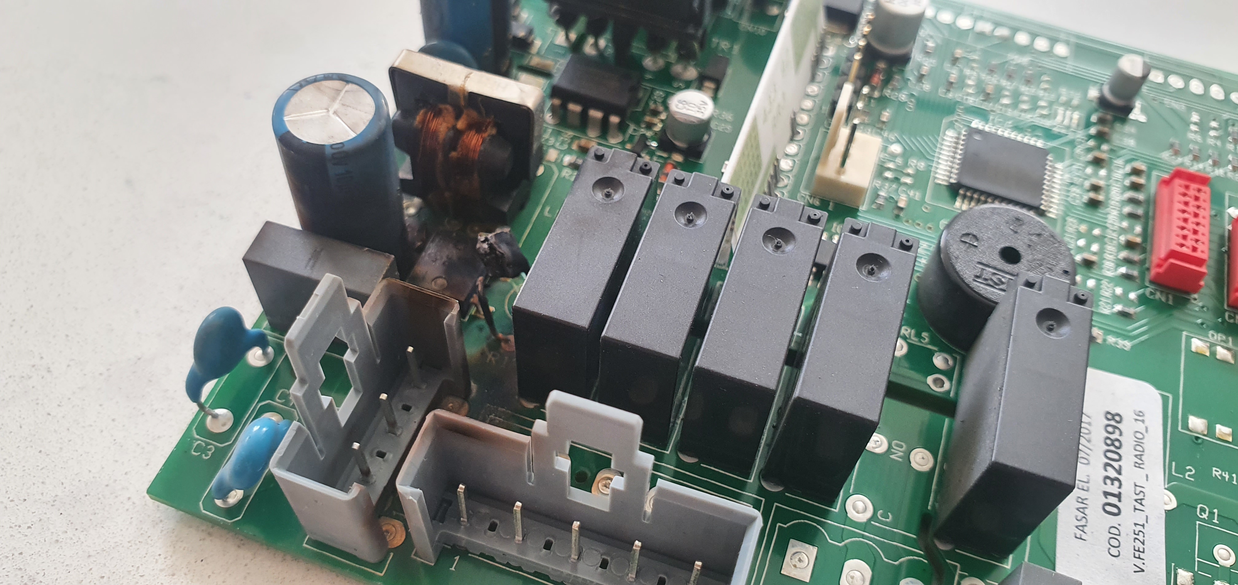
Attached a picture of the sad board.
Any advice very appreciated, I may try to get down this/next Thursday for electronics night and pick your brains
Indeed! Looks as if it’s Bluetooth-controlled or something daft like that.
The least worst thing that could have happened is that DB1 (bridge rectifier) has failed, and taken out R1 (probably a fusible resistor, for inrush current limiting) and possibly L1 (bifilar interference suppression choke). DB1 can be replaced with any old bridge rectifier of 400V or more rating; L1 can at a pinch be wired across but that’s naughty so should be replaced with any old suppression choke from another power supply; no idea what value R1 is (something around 47 ohms?) but is safety-critical so would need another fuse if not replaced by a fusible resistor.
Unfortunately other components could also be damaged, particularly IC1. As IC1 hasn’t been blown to smithereens I’m guessing it’s not the cause of the fault but could have suffered from the after-effects.
A drastic fix would be to give up on the power supply and use another unit. It looks like it produces two voltages. One will be for the relay coils - perhaps 12V or 24V (see what’s printed on them) - and the other 5V (judging by IC4). You can regulate the former down to the latter.
The primary purpose of the VDR would be to protect the power supply against transients I think, so it would be wasted on the output of the relay. Also where to put it as I am guessing those four relays in a group all switch live to different tappings on the motor (possibly with capacitors) via CN12. It’s certainly in a peculiar place, though.
I don’t like what look like grease deposits on some of the components. Looks like the PCB is not properly isolated from the air stream.
So I should have probably shown a picture of the full board. I’ve also found a replacement board on an Italian site for reference… It may or may not provide some more context.
As for fancy functions, it has a 433 Mhz remote and some timer functionality, LEDs, etc etc. I was hoping to hook it up with Home Assistant and my Sonof-RF and a air quality meter (and potentially smoke detector) to auto turn on… but it’s broken so
The appliance importer has come back to me with a quote of £200 for a new board to be shipped over. Of course, there’s likely a chance that the fan could be broken too…
CN9 provided power to the unit from standard 240v 3-pin fused plug in a socket within the cooker hood.
CN12 is power out to fan
CN14 is power to LED driver
CN1 is out to the push-button and LCD display control
So I guess my options are:
Just pay the £200 for the board
Try to revive the PCB, possibly spending a bit more time reverse engineering, and cross-referencing the retail PCB photo above
I think it’d also be wise to try to identify whether the fan is OK or not. There’s no labels/identification on the fan itself, but it has 5 wires connected to PCB (CN12). I could probably figure out what went where to try to drive the fan with an external power supply.
Can I state the obvious here (forgive me) but working on mains voltage power supplies can be inherently dangerous – especially the risk from the urge to test and probe them when live and outside the case
So, I asked the importer about the fan - I definitely don’t want to spend £200 on the PCB just to find that the fan is bust too.
He says that the component was an NTC thermister, and that the factory is confident the fan motor would have not caused this type of failure…
So, current thoughts are to try to figure out what value NTC thermister I would need to replace it with, and give it a shot … Looks like the NTC only goes to bridge rectifier so I would assume the current will be relatively low. I might try a bigclivedotcom style reverse engineer to identify the circuit paths and figure out what’s drawing current through that NTC.
Other thoughts are that I could just bridge it out and put an inline socket surge protector in …