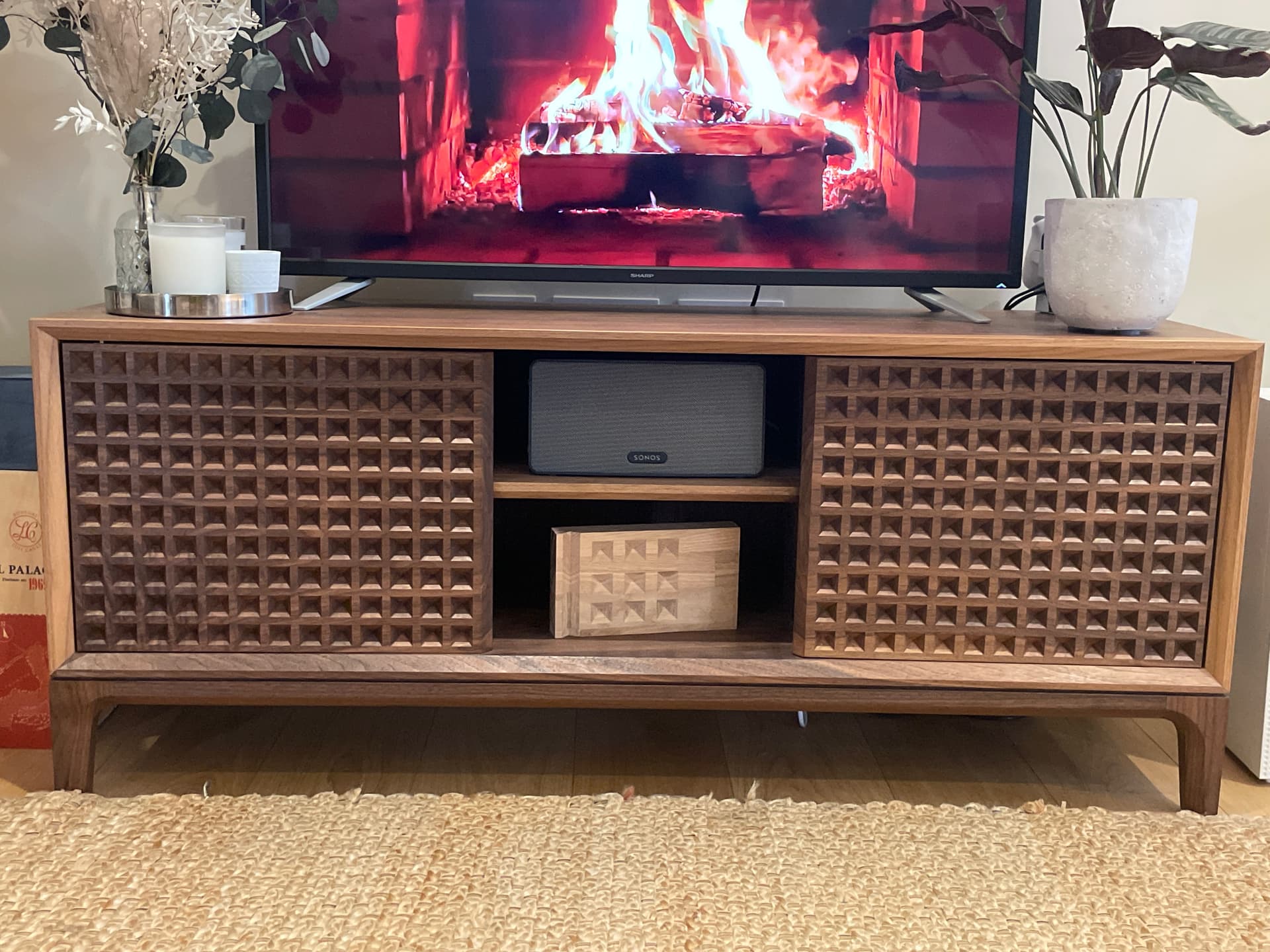
This is a bit overdue, but having recovered from a bout of mild illness last week I’m feeling the need to be extra productive and check this write-up off my to-do list. This is the final large piece of furniture that we can fit into our flat! Click through the following sections to find out more about the process of designing and building this thing!


Design
As usual, the longest part of this project was actually deciding what I wanted to do. I’d put together the first design over a year prior to starting the build, shortly after I’d put together my coffee table (link). The designs were done in Fusion. After putting these together I dropped this for a while in favor of other projects:


After finishing the futon (link), I revisited the TV stand. I saw this wonderful piece in the British Museam and appreciated how the carved grooves interacted with the light.

That was inspiration to start drawing up a new idea for the stand, with emphasis on the door panels using similar grooves. My last few projects had made use of gentle curves and round surfaces (side table, shelf), so along with the zig-zag pattern I went with a more boxy form. Proportions and details like the chamfers were continuously tweaked:


Before starting the full project I ran a few tests with different settings (angles, depth, etc) for the zig-zag pattern. I’m glad I did, because I ended up not liking it very much.


While going through the process with the v-carving bit, I came across how to create inverted pyramids on the CNC. The shadows hit the surface differently depending on the ambient lighting and your position in relation to the surface; it’s dynamic and visually interesting.

I ran a couple of tests on blocks and stared at them on my desk for a few days while redesigning the doors. I put together a couple dozen variants and stared at them for a while before deciding on one I liked.


Getting Started
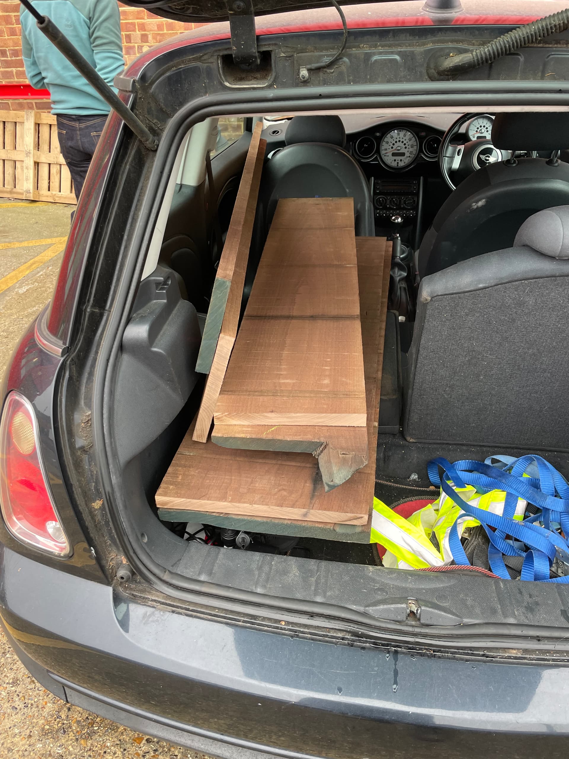
With the design part settled (though the final door pattern fluctuated throughout the build), I made my way over to SL Hardwoods with @duncank to pick up some timber; here it is roughly cut to size to fit in the car. Even though I design everything on the computer, I still do my cut lists the old fashioned way:

Next up was milling everything. Most of the boards went through the planer and thicknesser except for the door panels which were a little bit too wide; those went through the CNC and did not come out quite as flat.

Now that the actual surfaces of the boards were visible, I could lay them next to each other and decide which orientation I wanted each to be in for final cuts. This part was a bit annoying as the spare board I’d planned on chopping up into shelves and internal panels (and had rough-cut the others accordingly) ended up being the nicest looking. It had this beautiful lighter tone that would look very nice exposed on the edges of the body. Making this change would mean that instead of each panel being two wider pieces as planned, it would need to be three more narrow boards, so arranging everything became a bit of a puzzle. This process took a full day, multiple benches, and lots of small pieces of tape.

I’d noticed from my coffee table build that walnut has this interesting property of changing tone depending on your viewpoint; two adjacent pieces may color match from one angle, but contrast from another angle. I have no idea what causes this, but being aware of it I was able to take it into account when arranging the boards. Notice how from one angle, the side with the remote looks darker, then from the opposite side looks lighter:


With everything marked up, I cut the boards to final width and roughly to length. Remember, you can always make pieces smaller, but not larger!
PANELMANIA
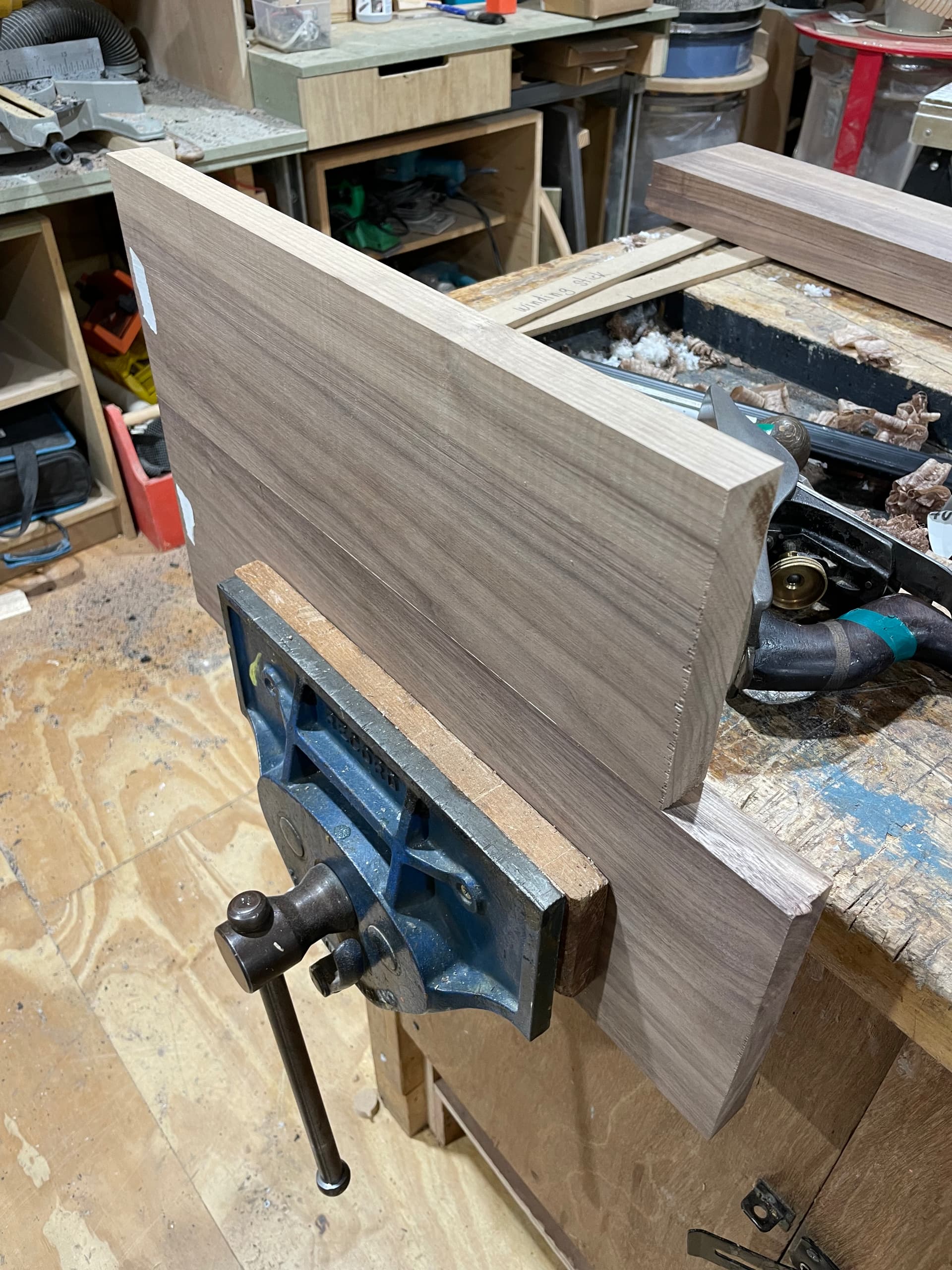
After, I could proceed with a bunch of panel glue-ups. The jointed edge off the planer is ok, but they can be made perfect using a hand plane. To do this, place the boards edge to edge and look through to see any light coming through gaps. Take down the high points on the clamped board then re-check. Make sure to use a straight edge while checking as well. when happy with the jointing, mark out and put in some dominoes (biscuits work as well) for glue-up alignment. The glue-up itself happened after a final dry fit with clamps and cauls. After gluing, I used a hand plane to knock off the glue lines. This project entailed doing this 7 times (top, bottom, two sides, two interior panels, and shelf)


Final results, barely visible seam!

The Box
The panel saw table helped greatly with getting accurate miters. Multiple test cuts were made first and measured to make sure I had accurate angles. When measuring for final cuts, relative measurements are more important than absolute measurements. Taken another way, it matters more that opposite panels are the exact same length, rather than each one being an exact length to the exact millimeter. This means measuring a single time and using a stop block to replicate cuts.


With the outer panels cut to size, I used dominoes to help align everything.


Interior panels
The vertical interior panels need to slot into grooves in the main body of the unit. To do this I cut two pieces of scrap to length to measure out where to cut the groove, and clamped boards spaced by the panels themselves to create a template to follow with a router trim bit. I used these same two scrap pieces to mark out each groove location to ensure they all landed the same distance from each edge.


Legs
The four legs in the design required squat, rectangular pieces that would then be cut away to their final shape. To get pieces of the required thickness I arranged some leftover boards into a stack, keeping in mind color matching and the aforementioned variation from viewing angle.


After the glue dried, I squared it on the planer and thicknesser then cut into four equal lengths. Final touch ups were done on the hand plane.


The aprons were cut to length, and tenons cut on the spindle moulder.

Fine tuning was done by aligning to the bottom panel of the main body, rulers not necessary for the final measurements.

The mortices were marked with the marking gauge then morticed on the morticer. Final touch-ups were doen with a chisel.


Everything was dry-fit then tweaked until they easily came together.

The leg templates were cut on the CNC, aligned and marked, then rough cut on the bandsaw.


Everything laid out:

I used the domino to cut out attachment points for the aprons using a similar method to what I used on the coffee table (link).

The legs were held together with a strap clamp, aligned to the bottom panel of the main body, then glued.

After the glue dried, the legs were carefully routed into a more refined shape with the CNC cut template

The router bit wasn’t long enough to fully clear through the legs, so I cut the corners out manually.

The final chamfer was added, making sure not to accidentally over-cut by allowing the router to fall over the edge of the leg. Those ends were made flat using a sharp chisel and hand plane.

The shadow gap was made on the router table

Doors
Before cutting the final design, I made a test piece in MDF to make sure I was happy with it:


Then it was time to go for the real thing. I cut both patterns together and marked out the cut lines for the board.

The panel was then cut to size on the table saw.

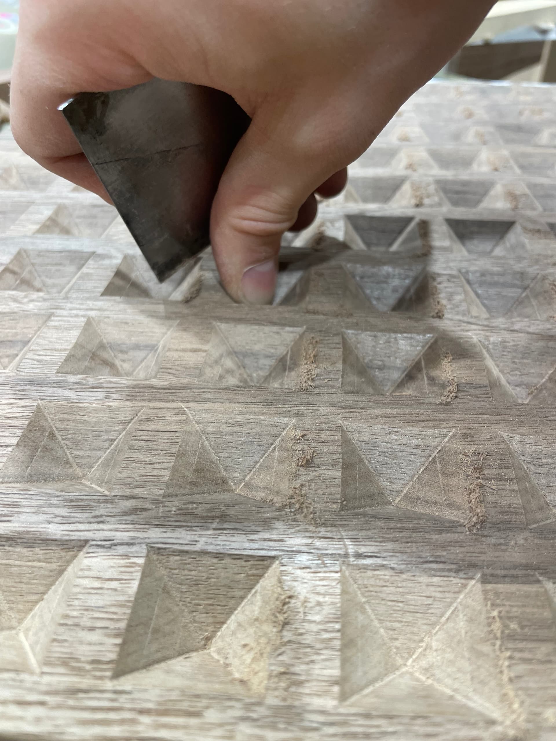
I then painstakingly went over each facet of the door with a cabinet scraper to remove milling lines. I would’ve saved a lot of time had I just bought a new bit!
Pre-glueing Touch-ups
Many of the final details of the body needed to be completed before gluing everything together. The outside chamfers on the main body, as well as on the shelf, were done with a router with multiple passes, and then touched up with a hand plane.

The holes in the side panels were done on the CNC, and the chamfer added with a router.


Box Glue-up
This part manages to remain dicey in every project.
The main body had a lot going on, having to align not only th eoutside panels, but also the inside vertical panels while keeping everything aligned. My dry fits came together square, but of course it wasn’t aligning when the glue went on. Thanks to @joeatkins2 for helping to wrangle this together

Here it is put together post-glue up:

Rear Panels
The panels on the rear of the main body are veneered MDF. I filled some small gaps on the edges of the vertical panels, though this was largely unnecessary. I marked out where to cut the grooves for the panels, then routed. The corners were done with a chisel.


The panels were cut down to size on the table saw then fitted.

Holes for cables were cut on the rear panels on the two sides

It's got Legs
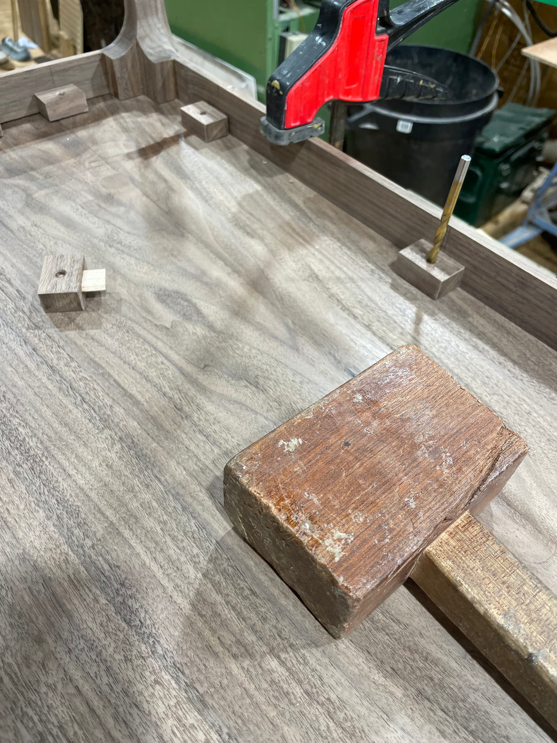
I slapped a bunch of dominoes into a leftover piece, drilled a hole behind each one, then cut to size to create the clamps that hold the legs to the body.


A drill bit and light taps of the mallet helped mark out where to install threaded inserts.

Finishing and Oiling
I’d attempted to do most of the finish with a hand plane and cabinet scraper, but I wasn’t getting the desired results (some minor tear out). I ended up giving the whole thing a light sand, progressing through the grits as normal.

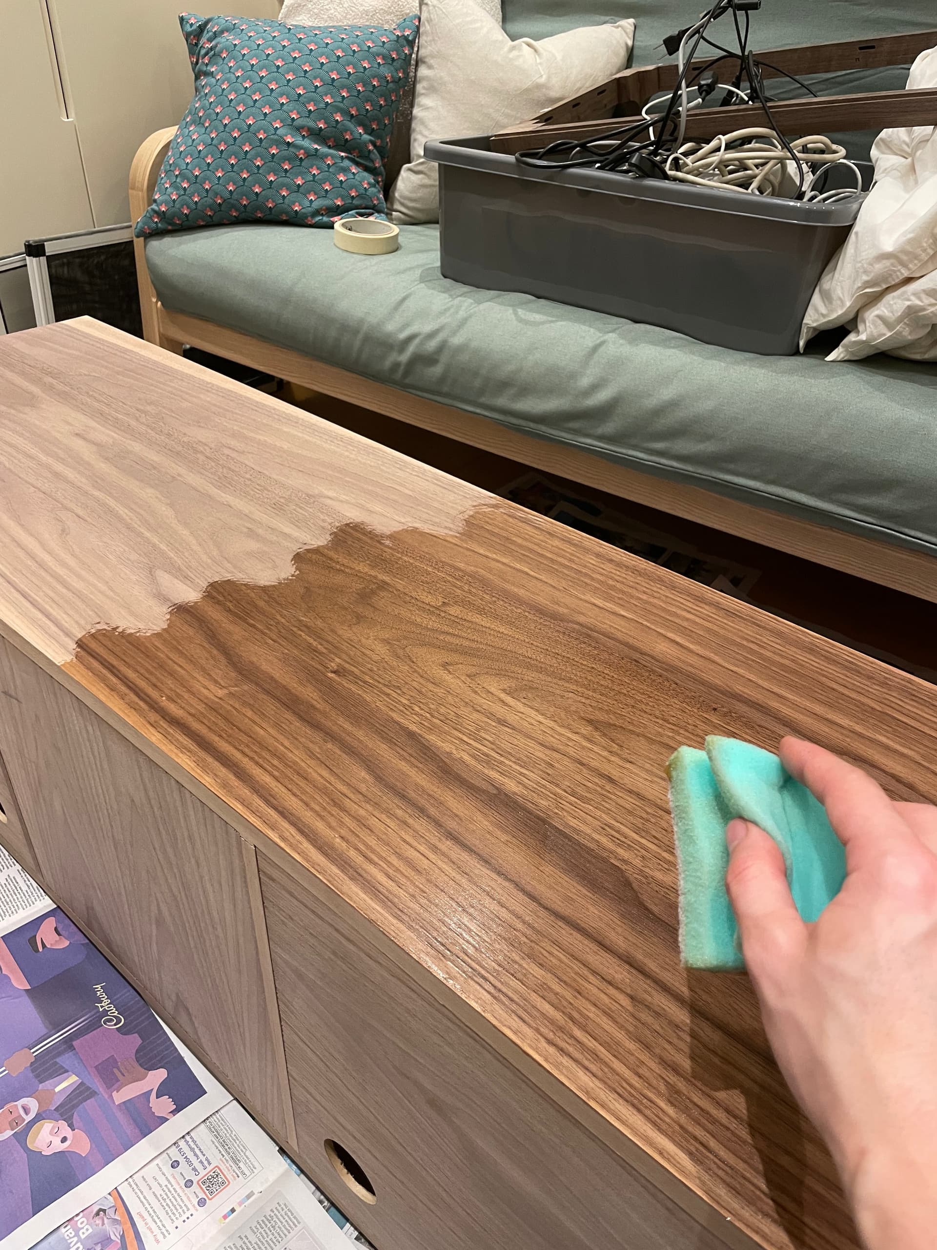
After taking it home, I applied an Osmo oil finish.
Final assembly of the legs:

Mistakes into Miracles
I screwed up one of the grooves for the vertical panels and ended up accidentially cutting it beyond where I’d intended. Left as-is, it would have created a visible gap after cutting the chamfer. To rectify, I cut the groove all the way through then shaped a color matched piece of scrap to fit. After the glue dried, I flattened it back out with a hand plane. Luckily it is very hard to notice unless specifically looking for it.


I gouged one of the aprons when routing out the legs. I filled this in with a small scrap and some planer shavings and made the bottom flat before routing the chamfer. It’s not the best fill, but you essentially have to flip the TV stand upside down in order to notice it.

As mentioned in the glue-up section, it was a bit of a struggle to get everything to align. The right rear corner of the body curved inwards slightly. Luckily this not noticeable unless specifically looking for it.
I smashed the back corner of the cabinet into a brick wall right outside our front door. I filled in the smashy bit with some resin and sanded it out.

I cut through the tenons on the legs when making the chanmfers, exposing some small gaps. I experimented with different filling methods (glue, sawdust. etc), but luckily they’re so low to the ground you don’t notice them.

And the biggest one… I purchased some cabinet hinges after doing hours of research to find ones that would fit, similar to the ones pictured below. As I was creating the boards I’d use as an attachment point to install them, @Keith asked what I was doing, took one look at them and said they wouldn’t work as they wouldn’t have enough throw to clear the heavy chamfer. I’d thought I’d considered this, but after another check it of course turned out that he was correct.

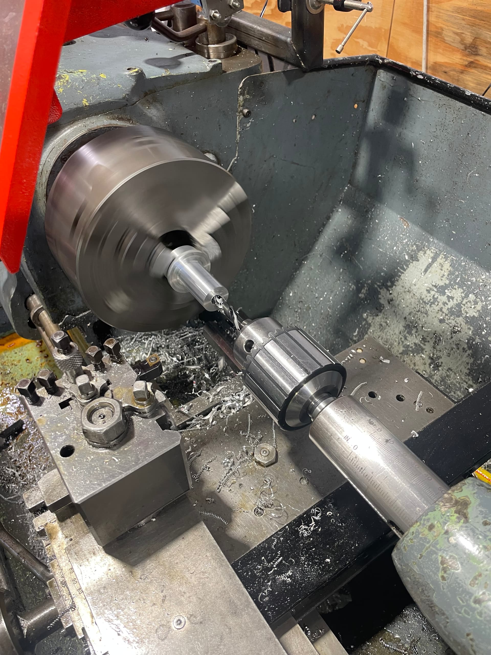
Metal Lathe, because of course that was necessary (see: Mistakes into Miracles)
I actually moved the TV stand into place and used it for a couple months before making up the hinges. If you look closely at the first picture in this post, you can see that the doors are actually just resting on their bottoms; they’re not attached. I wanted the doors to “float”, with a small ~2.5mm gap around the edges of the door. Cabinet hinges are adjustable, which would have been easy , but as mentioned in the previous section those weren’t an option. Keith proposed a pin hinge, but those aren’t adjustable either, or at least I couldn’t find any. A few weeks after finishing the rest of the cabinet, the metal lathe was being put into service, and this problem was my excuse to start using it.
Design constraints
- The height of the door in the frame needs to be adjustable to be able to match the sizes of the gaps above and below
- the angle of the door/hinge needs to be adjustable so the door sits parallel to the frame
- The pins need to be able to retract, or otherwise get out of the way, in order to install the door
Thank you to @joeatkin2 @VintageSteel @scythian and @stefanoromano for your help getting through this!
One way to put a square piece into the lathe to to first make a ring to hold it in:

This lets you fit the bar into the three jaw chuck. the top and bottom hinges have holes drilled like this:


The slots were cut on the mini-CNC:

Here are the final top and bottom pieces. The top has an internal spring and pin to be able to retract and fit the door:


Both hinges immediately prior to installation. The top hinge has a bit of extra space to allow for horizontal fine tuning. It’t hard to see, but there’s also a small brass cap that was installed in the top of the frame to allow a hard surface for the pin to pivot in. The threaded peg at the bottom comes up through the bottom of the TV stand through a threaded insert to allow for the tuning of the height of the door.
