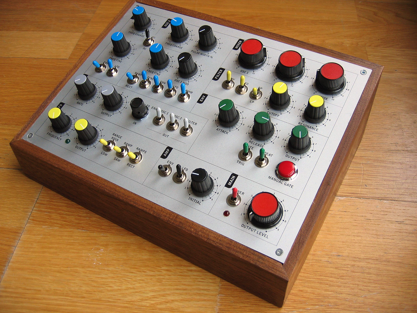
I made this DIY synth many years ago - it was my first music project. It stopped working so I did quite a lot of work in my spare time over the last months getting it running again, with the benefit of a bit more experience.
I fixed up the original wiring, but also had to replace a couple of the circuit boards, one of which (power supply) was home-etched and not good quality, the other (Midi -> CV) was not working properly and was also not of good enough quality to be reliable in the long term.
So I designed a couple of PCBs based on some open source circuits and got them made up by JLCPCB.
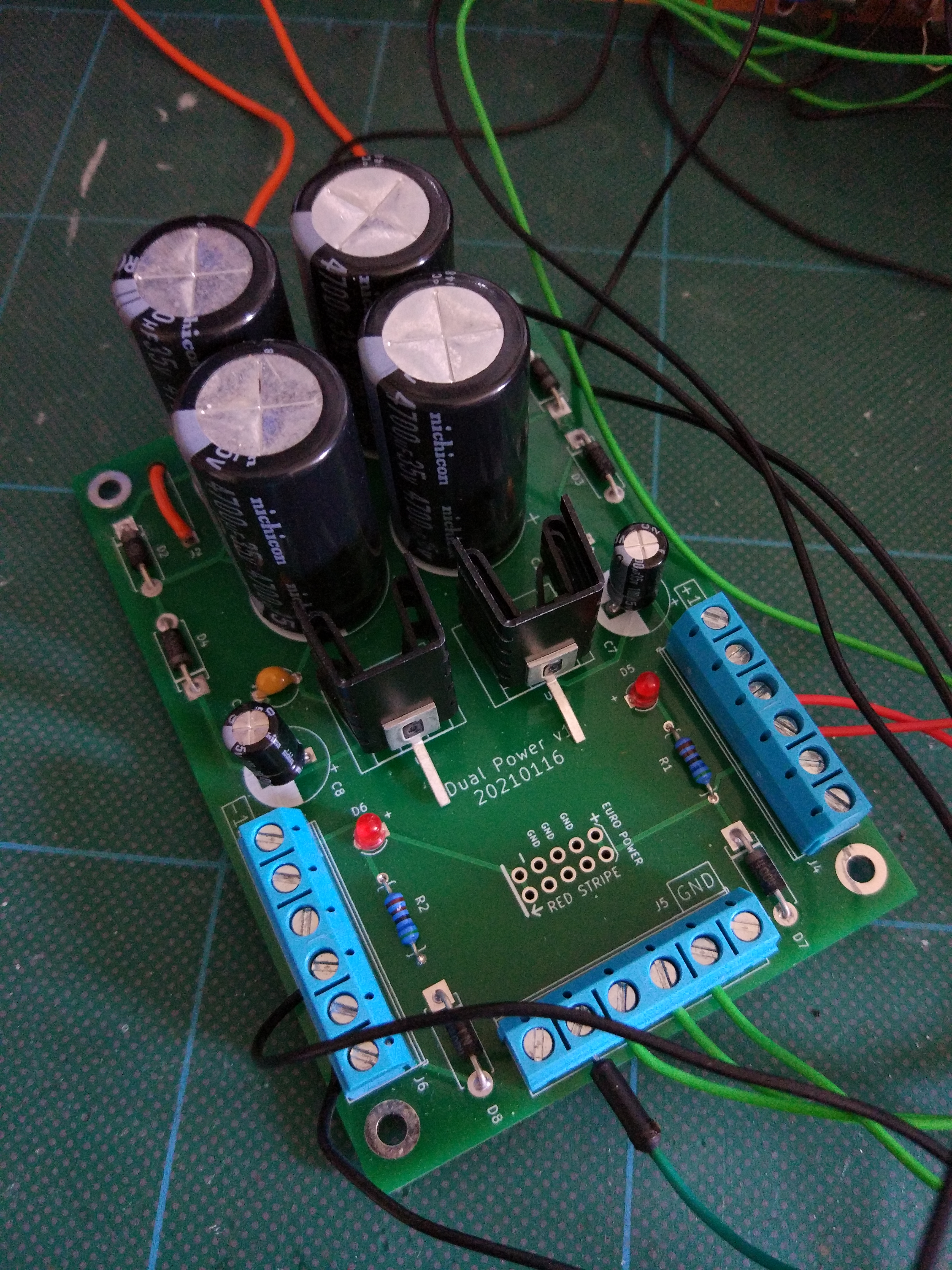
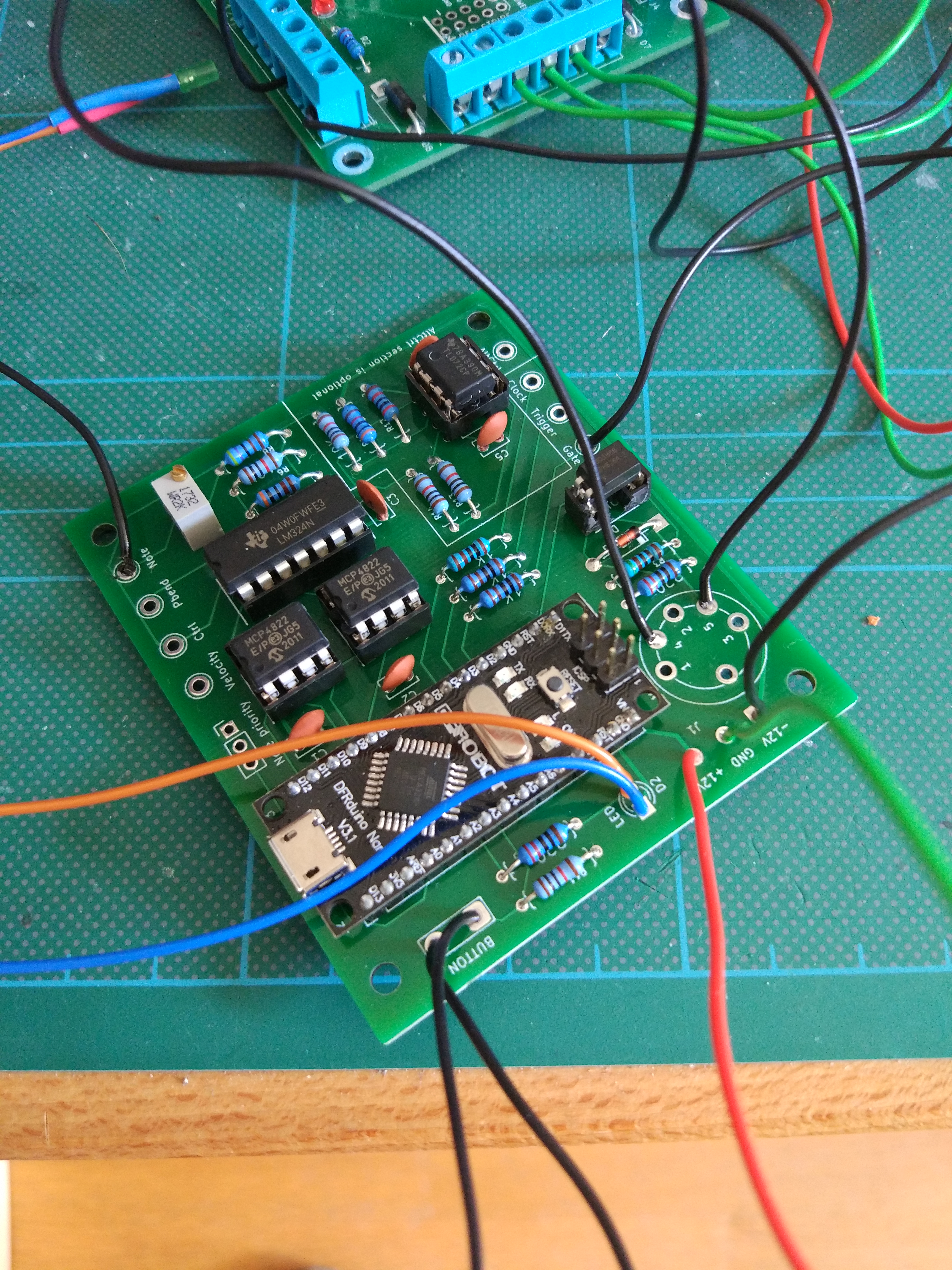
I have a few spares of each, if anyone is interested. The power supply is +12/-12V and has a space for a Eurorack header, so could be good for a small Eurorack box or a test setup. There is more info about the Midi->CV circuit here. It’s based on an Arduino nano.
Now that it’s working I recorded a few sounds for posterity. Gives an idea of its capabilities. It’s mainly a noise machine but it can be quite musical too.