Hi All
Joe @joeatkin2 and I have been having entertaining conversations about real-life electronics, so I’ve been measuring a few things just to see if what he says is actually true. I thought I’d share a few lab results.
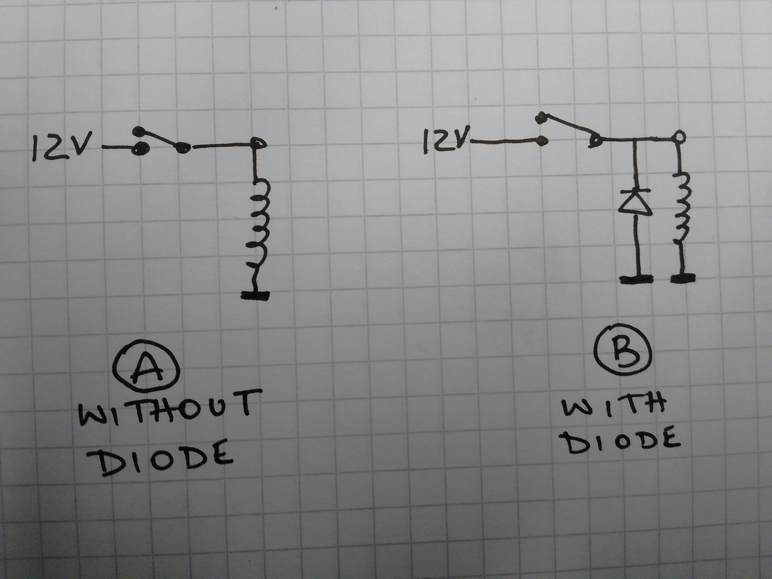
Every textbook will tell you that you have to have a diode across an inductive load such as a relay or motor to catch the voltage when the inductor goes off. That is, don’t do A, do B.
Q. But how bad is it if you don’t do it?
A. About 300 V bad.
The following scope traces show the voltage at the top of the coil of a 12V relay as it goes off. The relay is a pretty ordinary 12V Omron relay. The diode is a 1N4004, very usual 1A diode.
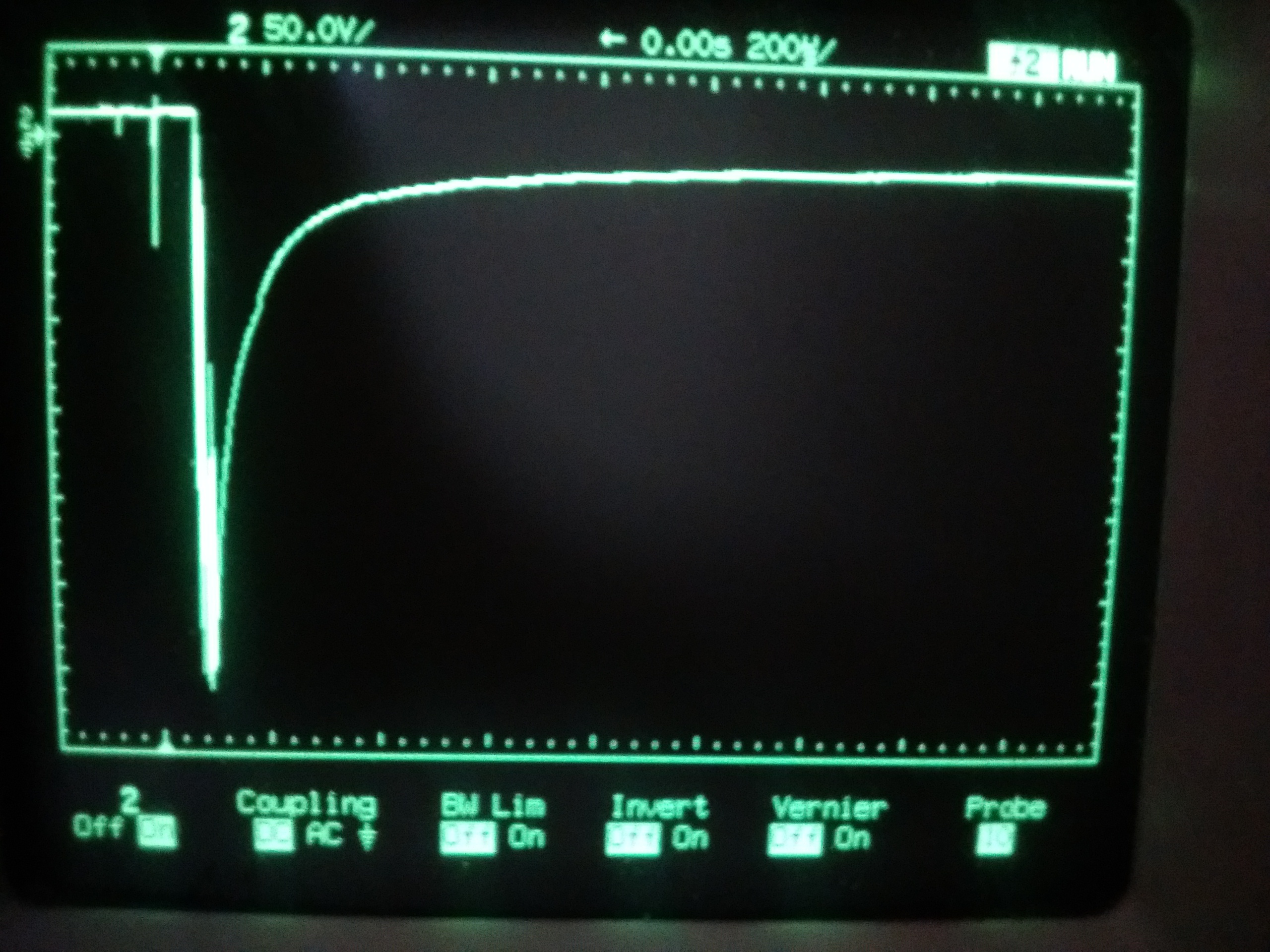
Circuit A without diode gives a 300 V negative transient, which is likely to be enough to destroy any transistor which might be switching it.
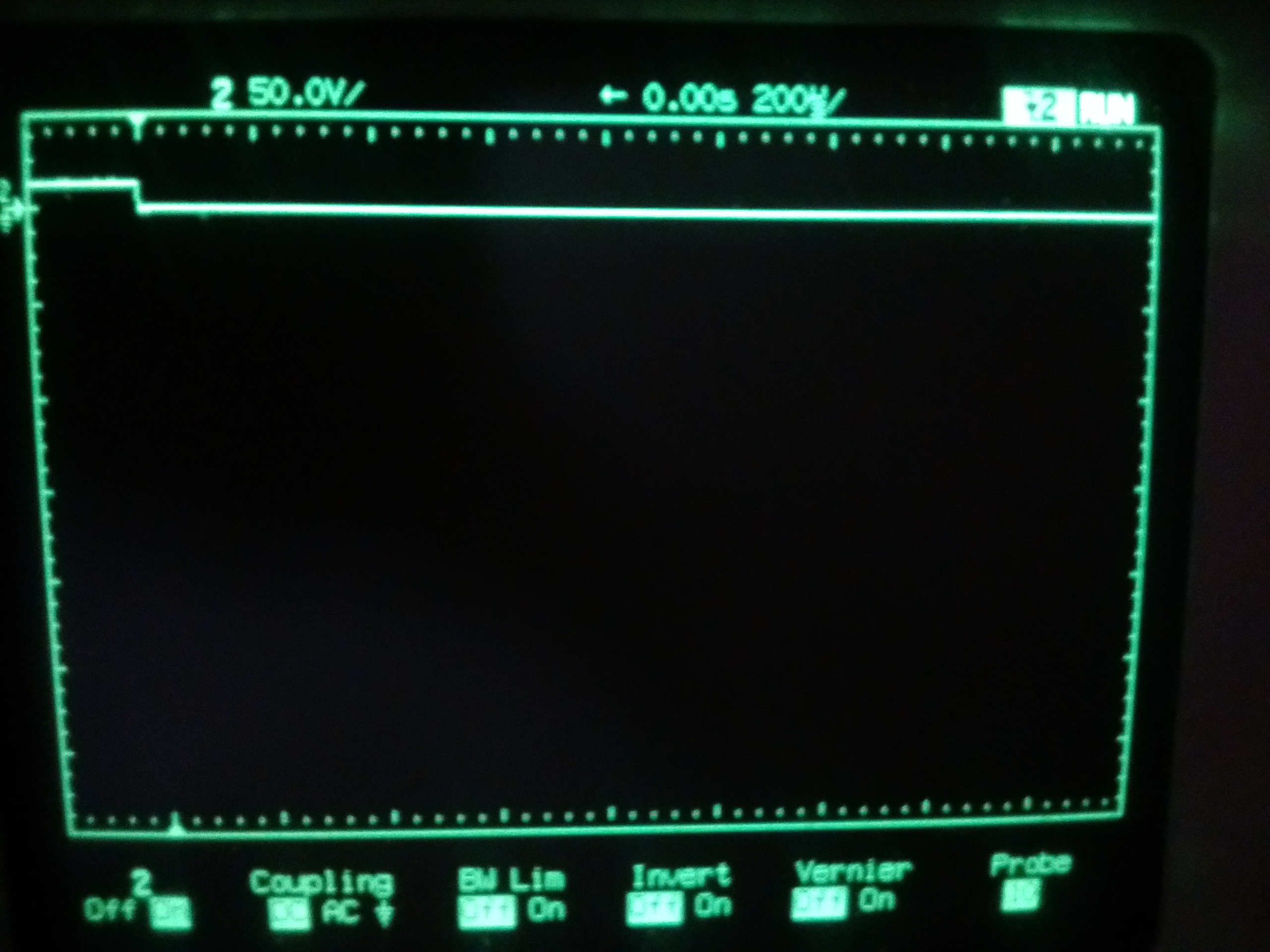
Circuit B gives us a nice little 12V down to 0V as we’d expect.
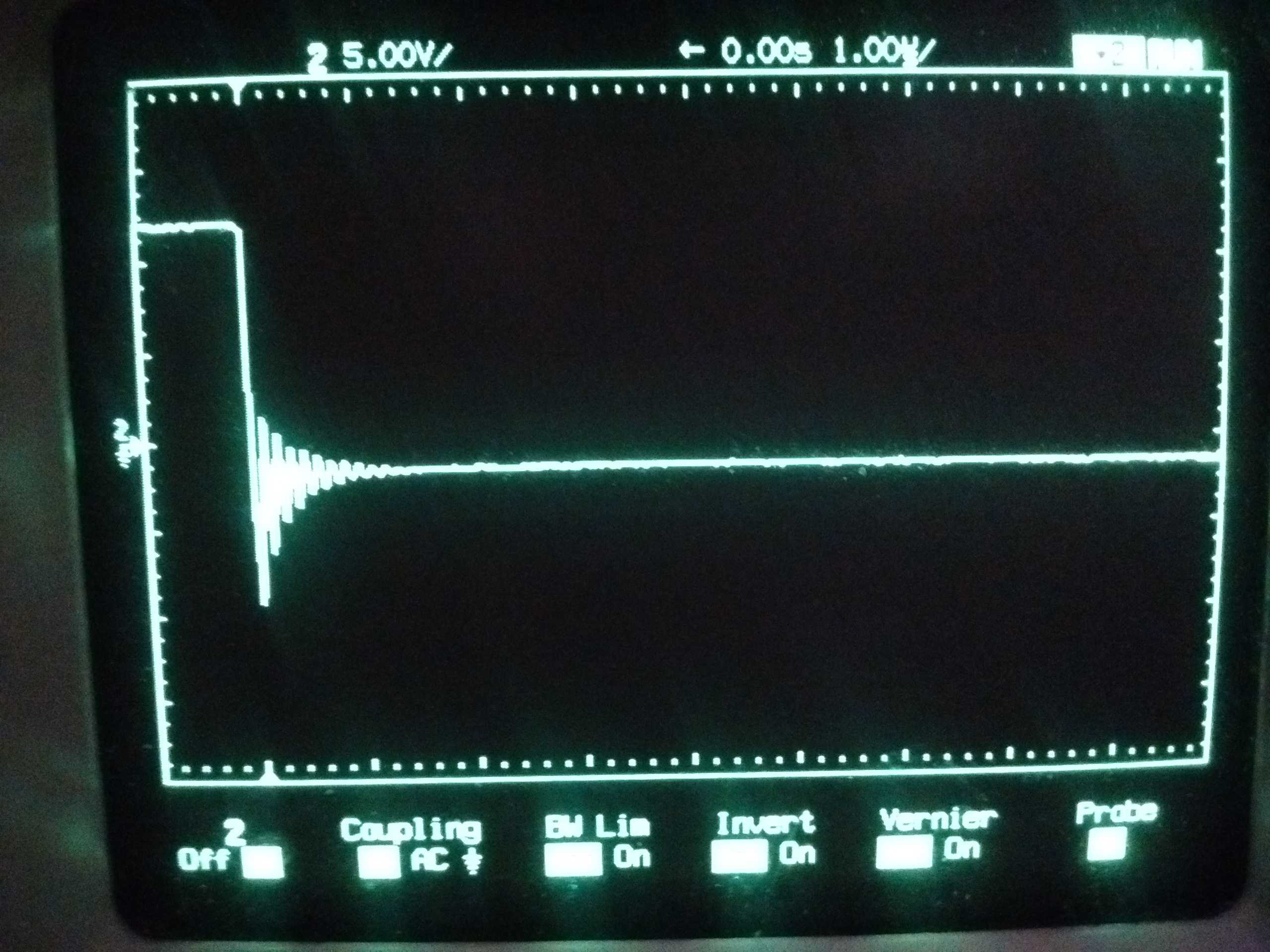
If you zoom in on that, the 12V step actually rings a little bit, like this:
Joe’s score: True 1, False 0.
Kind regards to all,
J.
