Mechanical Dot-Matrix Display

Hello.
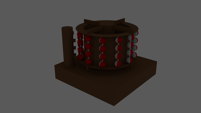
I’m trying to build a mechanical dot-matrix display of 32x8 pixels. Each “pixel” is a spherical wooden bead with a hole through, painted on one side. Rows of eight beads are mounted on vertical metal rods, and 32 rods are arranged on a rotating cylinder. The beads are fixed vertically but free to rotate around the rods, so that they can either appear painted-side in or out. (*1)
The cylinder sits on a rectangular base and is turned by a motor; it constantly rotates clockwise so that the message appears to scroll from right to left. It can be slowly updated by a tower, also protruding from the base, containing eight photosensors and solenoids, which detect the current state of each bead as it goes past, and gives it a push if it’s in the wrong position. (*2)

*1 I’m not sure how to do this but I maybe I can glue smaller plastic beads to the rods to act as spacers, and the beads can balance on them.
*2 As the display is rotating, I just need to gently push against each bead to force it to turn in the opposite direction. This might not be enough to turn a full 180 degrees but as long as it eventually gets there, that’s fine. The photosensor detects what fraction of coloured/uncoloured bead it sees go past, to tell what angle it’s at. I can hopefully use an LED blinking at a given high frequency to cancel out the effects of ambient light.

Does this sound completely crazy?

1 Like

Yes it sounds pretty crazy! :slight_smile: But in a good way.

I can’t quite picture it as you mention rows but it sounds like they might be arranged in columns?
Re. the rotation of the beads, you are looking for binary states, is that right? Maybe you should be using some kind of electro-magnet arrangement so that each bead is either repelled or attracted according to the type of charge present, forcing it rotate in 180 degree steps. Pushing them with a solenoid sounds a bit haphazard, but maybe that is part of the effect you are looking for? Gradual transition from white to black or vice versa?

Could look great though, I look forward to seeing it! :slight_smile:

Yes I meant columns, not rows. Here’s an image of the rough idea I had in mind (with fewer pixels)


The electromagnet idea sounds interesting but I’d need to embed magnets in them, which sounds time-consuming for 256 beads! They are currently made of wood. The idea is just to push against them so that as the display rotates, they turn in the opposite direction. 32x8 pixels is barely enough for a HH:MM clock display, so they don’t have to update quickly.

Have a notch in the bar and use circlips that way there is no friction between the balls.

How about a motor behind each ball so that once it passes the sensor it then can be moved into place by a motorised rubber wheel with a solenoid to pull it in and out of contact with the balls.

1 Like

I was thinking similarly. One or more motors and light sensor(s) on a carriage mounted to a gantry. Either 8 motors to manipulate a whole column at once with one additional motor to move this carriage along the gantry, or have just one motor on the carriage to manipulate the beads and another to move it and the sensor up or down to the row to be manipulated.

Why is it round? I guess the gantry could be a rotating arm/carriage within the display instead with what I suggested :laughing:

Or have teeth on each bead catch on solenoids contained within the drum, magnets could be used to lock them into binary positions as they move past the bead setting solenoids.

I don’t know why it’s round, it just seemed to fit. The whole display part rotates. So the “gantry” can just be static, so easier to wire, and outside the rotating part rather than inside, so not catching on it as it turns.
I’m not familiar with circlips but they sound fiddly to do 256 times.

I was just curious as to what it would be used for, this is something I found similar: https://www.youtube.com/watch?v=9ddsGYWCHg8

I have another possible idea for a mechanism, I’ll can sketch it out when I get a moment. You could have the beads flipped by levers to set them in either of the two positions, each bead with its own lever gets trapped into position by a split ring and can only be flipped within a specific point in its rotation. In other words the drum rotates the columns of beads and attached levers against a column of solenoids used to flip the levers into the appropriate position, photo-interrupters or a hall-effect sensors could be used on both the drum and the solenoid-lever-flipping-column to read the relevant positions.