STL to CNC for a topography map

Hey all and hi @CNCtechs,

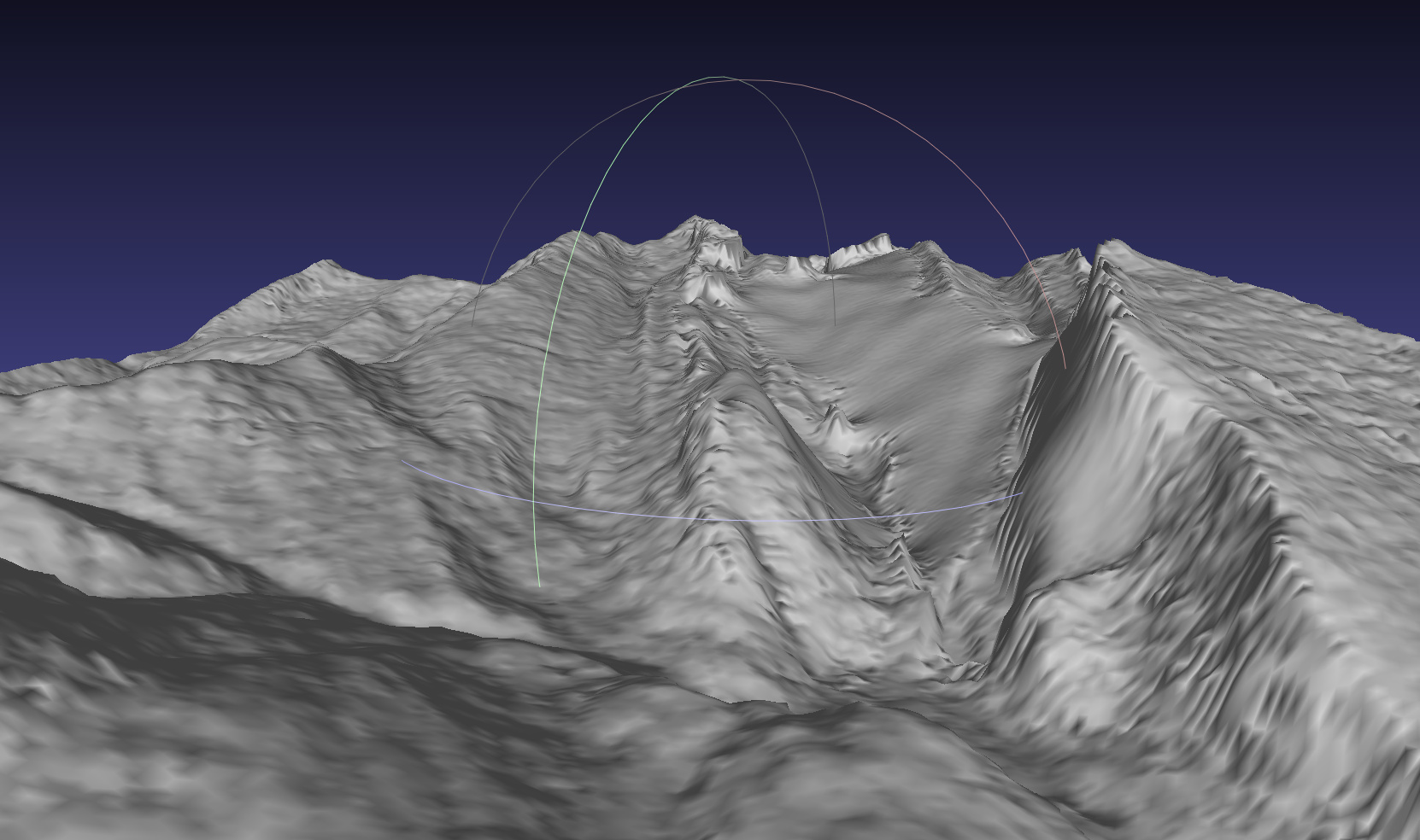
I am working with a topography map in .stl format. It is possible to import it in Vcarve but I wonder if it is the best way forward. My other option would be to work with fusion360 and then import the toolpaths in Vcarve.

Does anyone have experience with this and can suggest a workflow?

2 Likes

You don’t have to import into Vcarve but you can just get the G-code in Fusion and then put it straight onto the CNC.
I think @PReardon has done something similar.

The important thing is to make sure that the path is clear for the milling head to not bump into anything once you cut deeper. So on the small machine you can only really cut as deep as the tool stick out is, minus a few mm clearance.

Hi Clem!

No need to use both!

It will definitely work in Fusion 360 - I have never used VCarve for 3d so you would need to google that… but either package can independently do the CAM portion and generate the Gcode…

Let us know what you find out!

I would highly recommend doing it in Fusion, the tools for CAM are much better in fusion. I would leave vcarve out of the equation all together

1 Like

Okay! Happy to ditch Vcarve, I guess all I need to do is to import the CNC tools into Fusion360

Thanks guys

1 Like

We probably should create a tutorial at some point but the to-do list is ever growing.
There’s a bit more to it than that unfortunately but the basics aren’t too bad. I’ve walked Paul through it recently. Minimizing cut time is the name of the game. You have to design each tool path. Try an adaptive 3D tool with an endmill to start. Any 2D ops will ignore stepover and stepdown by default. Finish with a ballmill scallop or two parallel passes offset by 90 deg. I think the tool lib needs updating.

1 Like

Happy to see where I can help

1 Like

Yes it needs updating. There’s only one tool on there!

@PReardon when are you next in the space? Perhaps you can show me some stuff?

Actually no, there are a few tools on there…

Another option might be to use a slicer tool then cut the layers on the laser cutter. The resolution would then be determined by the thickness of the material you use and the number of layers you build up….

You might be able to do much more extreme contours than a CNC Z axis can handle. And also not have to worry about all the feeds and speeds for your g code.

Would also be a fun construction project once all the puzzle pieces are cut out….

Hi @ClemJ , I thought I replied to this sorry, how does this evening sound?

Hey, can’t do tonight, perhaps you are around this weekend?

Last night I did a quick video of how to use Fusion360 CAM for our desktop CNC https://youtu.be/riK6aTKOouA
As you work through the process, please leave feedback here! I am hiking the Isle of Skye next week but want to do a proper redo of the video in the future.

5 Likes

Amazing, I will definitely use that video and give some feedback. In about two weeks time when Im back from a work trip

Enjoy hiking

3 Likes

Looks great, I was a bit lost in places but that’s just my level of knowledge so would have questions but I’ll watch it all the way through and give some feedback, good work, I need to get up to speed on Fusion 360 for CNC as I’ve not used CNC since my induction ages ago with VCarve and all that…

1 Like

If I’m not in Australia when you go to CNC this I would be happy to be around and give you a hand