No I wouldn’t connect Dout to ground as if you send in data and it transmits out (can’t remember if it does this by default) then you will probably kill the chip.
Similarly I wouldn’t tie other unused pins to ground unless the datasheet suggests it. Yes there are lots of cases to tie unused pins to ground but I’m not sure this is one of them - if you do connect to ground then turn the pin high (i.e you send in the wrong data to chip by accident) then it will possibly kill it too.
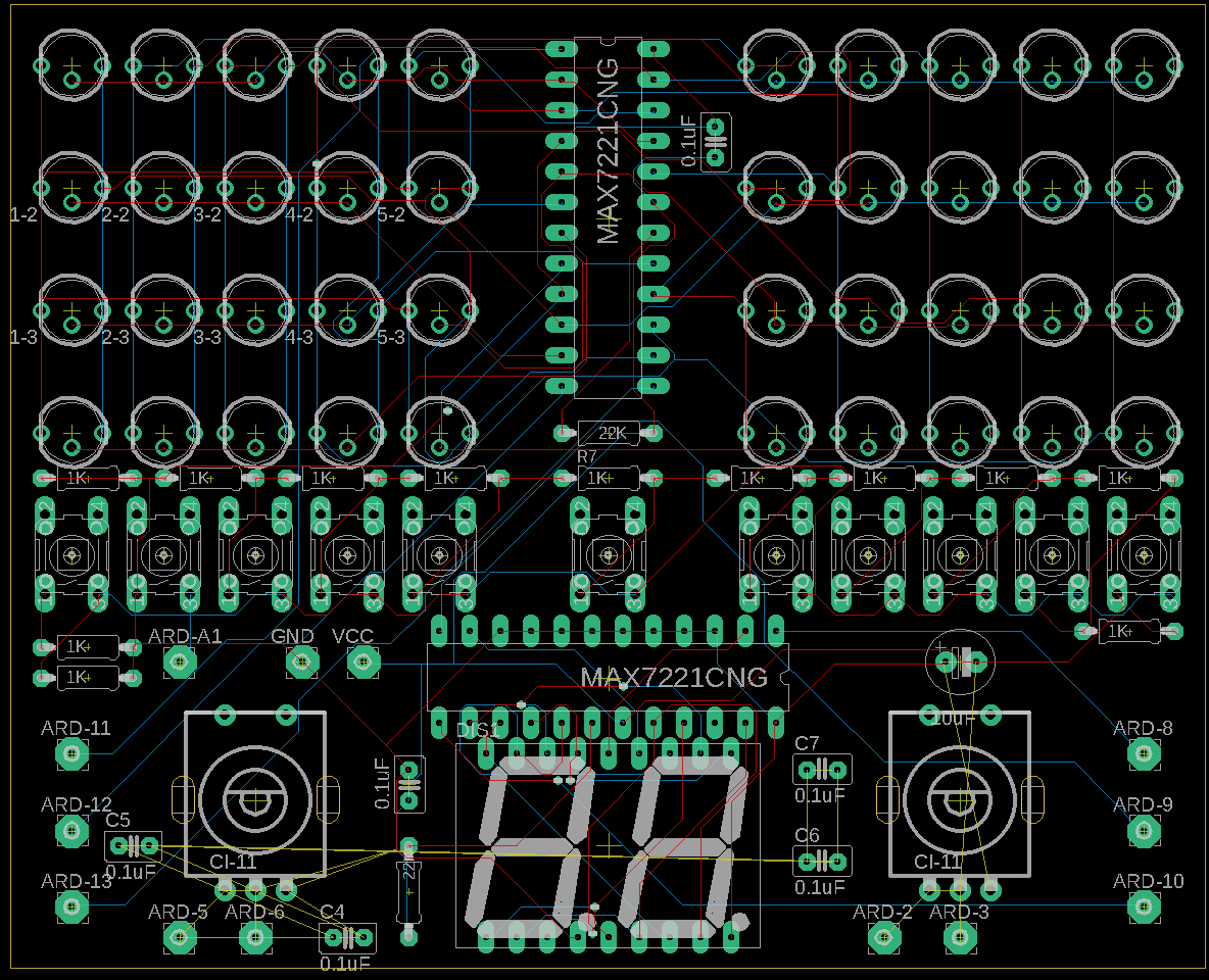
Caps - quick, simplified explanation - the reason they (0.1uF) are there is effectively to smooth out the voltage to the chip as it switches on/off a lot of times (the transistors inside the chip) and otherwise you can have issues with reliability as the voltage bounces around, damage to chip etc. You might get away with putting them further away or even omitting them but not recommended. I’d put the 0.1uF closest to the chip (i.e put it next to the V+ pin, then connect with a wire to it and also to all the grounds on the chip, as directly as possible, also using thicker traces - 0.5mm prob a decent width to start). Then put a bigger cap (10uF prob good) next to it too - this one is when you turn on the lights there is a sudden increase in the power the chip needs and your power supply won’t be able to supply it fast enough and otherwise the voltage again will drop etc. They need to be close so they can react really fast and help with the chips power quickly.
Generally I’d make the traces thicker as you have the space, but particularly the V+/ground traces (i.e the ones carrying most current) and try to make the power traces as direct as possible.
Not sure what CL-11 is - are you following someone else’s design?
Hope this helps - feel free to ask anything else/catch me in the space.
Cheers
Calum