Its not something i can capture easily.
As Im not monitoring it live on the device.
But i checked later and it was about 5v.
I need to see if I can capture both device and battery pack voltages.
But im pretty sure theres only one ADC i can use for this on these.
I might have to just monitor the battery pack instead.
Im setting one up now to sleep and report then sleep again.
Brains a bit frazzled at the moment so I may have to finish it another time.
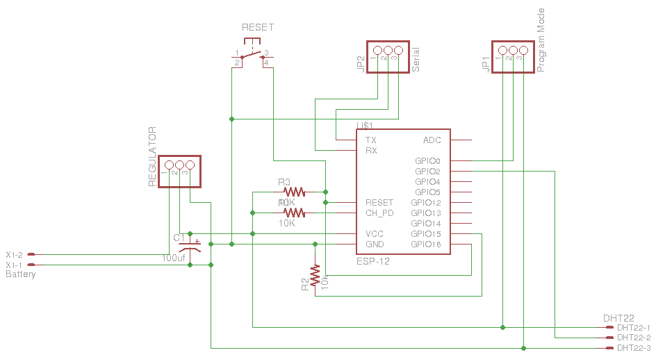
Ive added an extra capacitpr on the 3.3v side and the resistor to pull reset high for better stability.
I need to remove the wasteful led from the switching regulator at some point as well.
Well spotted, hadnt considered that.
Ill need to check the data sheet as it may allready have some power saving stuff built in or available that im not aware off.
If not I wonder if i can power it by connecting it to a gpio and setting it high?
Maybe not enough power and ill need to add some extra circuitry.
simple enough to use a gpio as an enable pin.
Found this nice snippet last night for a low power ADC battery monitor.
While i was trying to research smt components.
Would work well for monitoring the battery pack. Just adjust the voltage devider for the 1v range ADC on the ESP8266.
It uses a gpio to enable the voltage devider so it doesnt drain power all the time. http://www.microbuilder.eu/Tutorials/Fundamentals/MeasuringBatteryVoltage.aspx
Similar to what would be needed to cut power to the dht22.
This could turn into quite a useful little board.
With a little tweaking it could be a general use small IOT.
Found some 3.3v boost converters or step up regulators.
It seems you can get 5v boosters easily but 3.3v arnt very popular.
By pololu which seem to be a good brand. There stepper sticks are highly regarded in 3d printing.
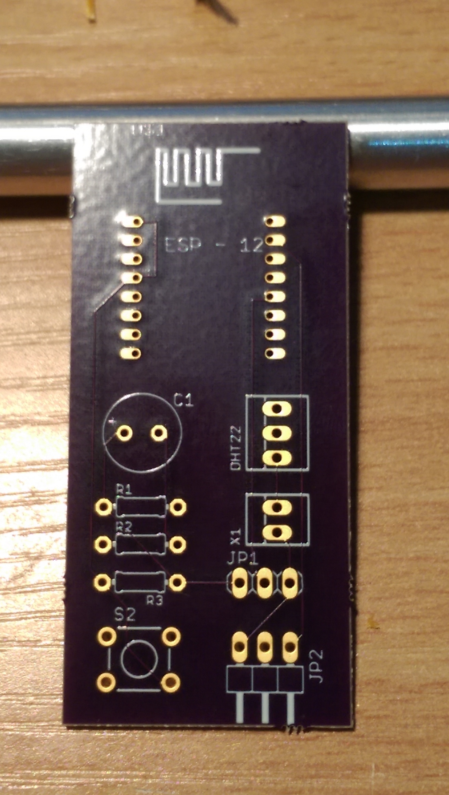
I got my boards from Oshpark on Saturday.
Ordered on the 19th arrived on 29th 10 days with the free upgrade i got.
Not bad for $13 dollars. Not great packaging though. Just a jiffy bag.
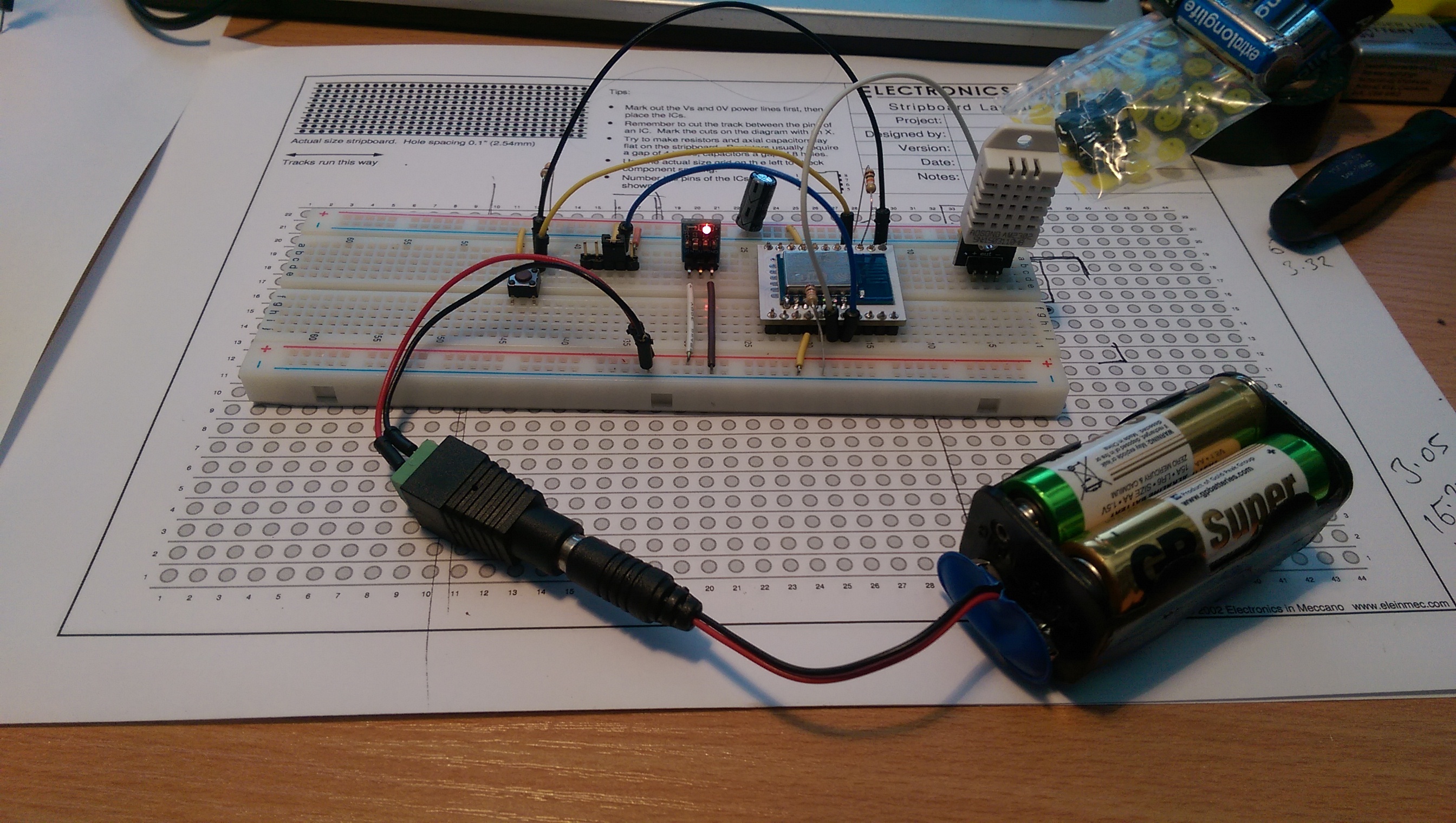
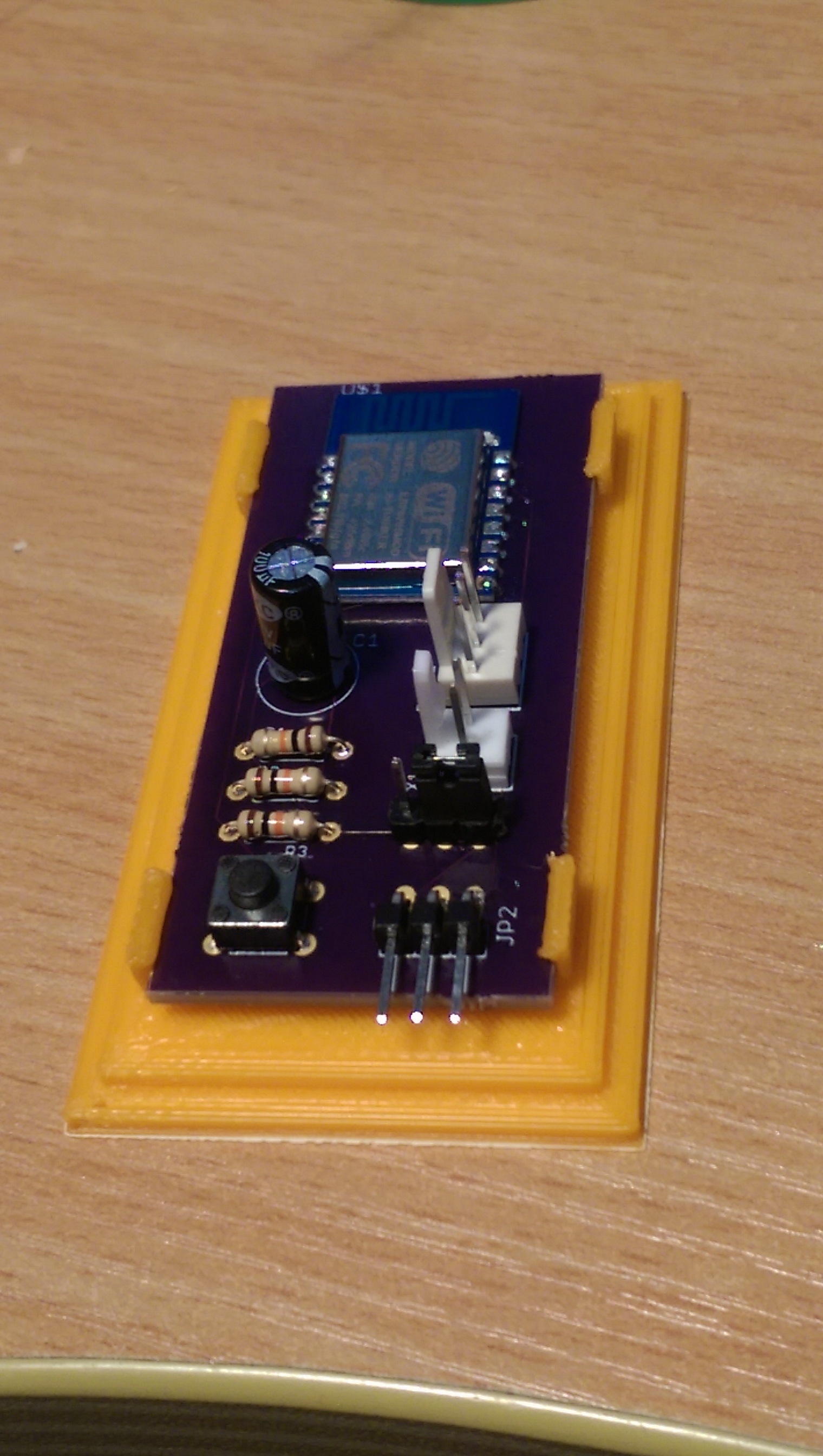
Got round to checking them and soldering components today.
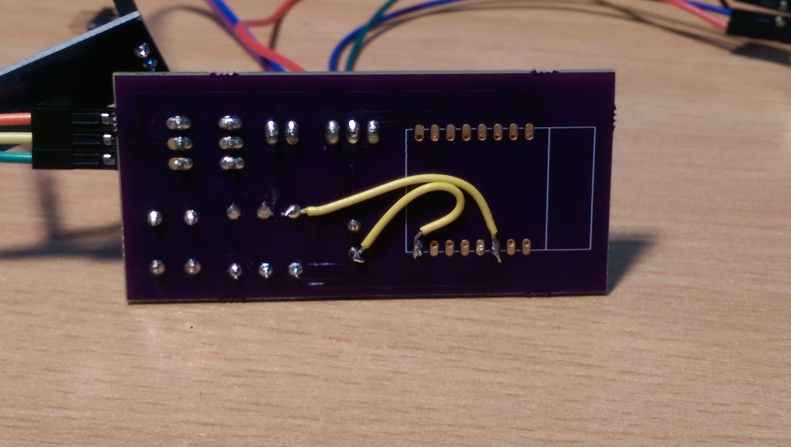
Im sure i checked it several times before uploading to Oshpark but must have not saved something before uploading the design. Obviously Oshpark dont do any checking themselves to catch mistakes.
Soldered on the ESP8266-12 to the pads and the rest of the components.
This one is for use with a 5v supply plugged in.
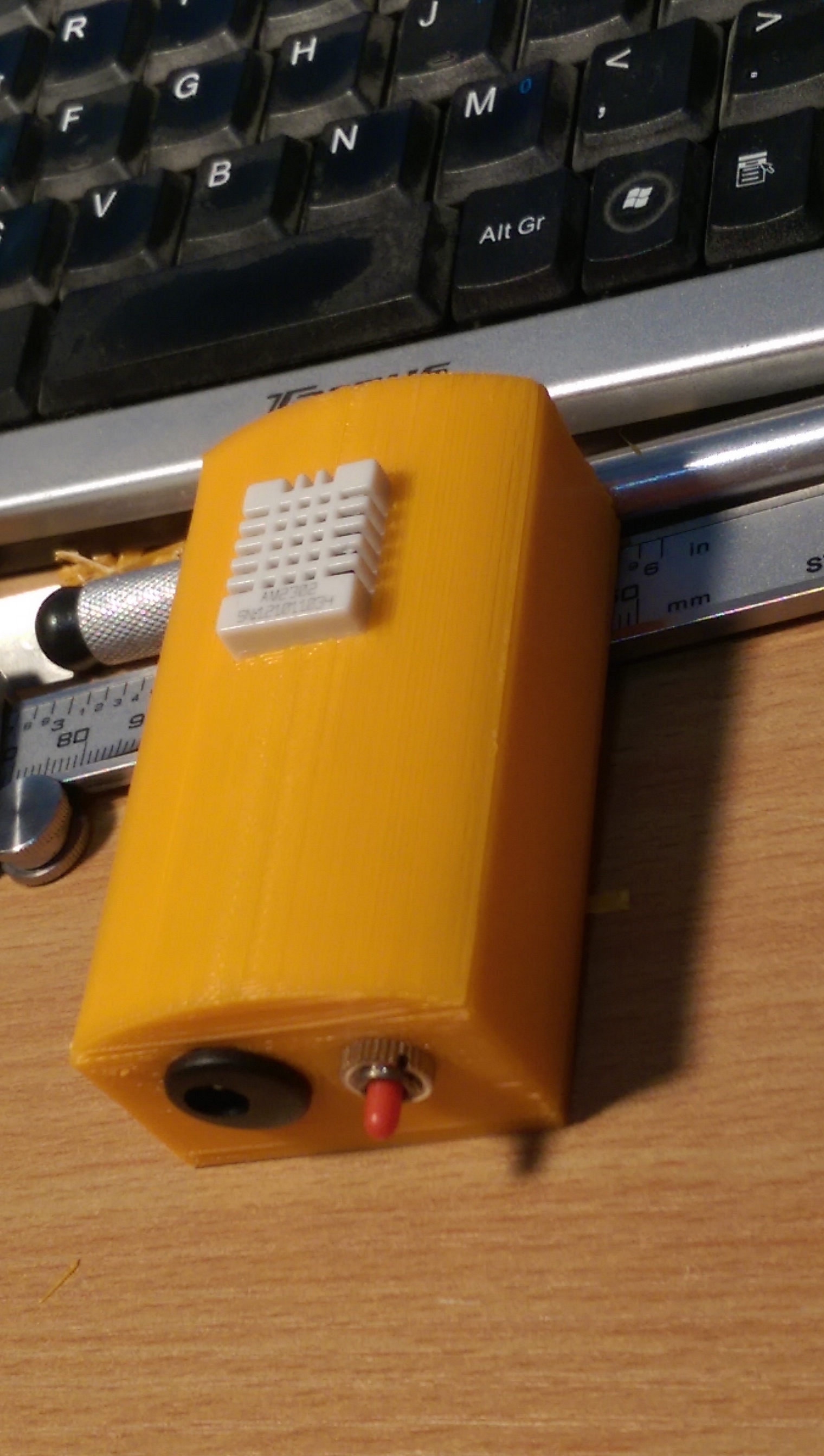
The orange isnt the final colour just what was on the printer ready to use.
It will be modular in several pieces so i can swap fronts, backs and bodies for different uses.
This one hss a mounting for a dht22 sensor on the font and holes for the power plug and a reset switch. I intend to have others for oled displays, batteries or other sensors.
Next version is going to be designed for surface mount components and incorporate the 5v to 3.3v switching regulator onboard.
I know, thats why i think i made a few last amendments, did the checks, but didnt hit the save button before uploading the .brd file up to oshpark
Need to alter my work flow a little.